
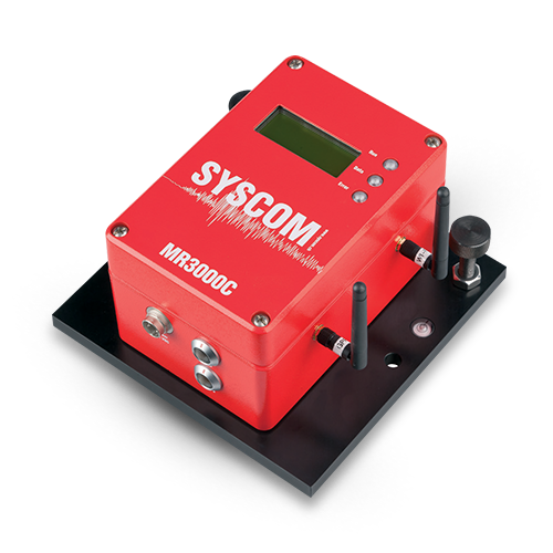
Blasting monitoring: MR3000C
Blasting monitoring is necessary in numerous scenarios, such as excavation, mining and building demolitions, in order to analyse the blasting’s impact.
When other structures are nearby those blasted, the vibration levels need monitoring, in order to assess possible damages.
MR3000C is a compact vibration/motion measurement system built in a rugged SYSCOM RED BOX.
The MR3000C is equipped with a new generation of electronic components, keeping the best features of the MR2002, but adding new ones, such as a reduction in size and weight and an increased computing power.
The MR3000C has been designed for different temporary and fixed measurements in the civil engineering and strong-motion surveys.
Applications


Major Features
- IP65 compact unit containing sensor, digital recorder and communications
- Internal or external sensor
- Triaxial geophone or accelerometer available
- External battery pack
- External display showing the most important information
- Removable memory SD Card
- Precise timing (GPS or NTP)
- Power over Ethernet (PoE)
- Wired & wireless connectivity
- Embedded Web Server for the configuration
- Event recording principle with multiple level triggers
- DDNS, OpenVPN, FTP push network capabilities
- Automatic sending of SMS and E-mail in case of event
Technical specifications
Data acquisition
- Resolution 24 bit
- Sampling-rate 50, 100, 200, 400, 500, 800, 1’000, 2’000 sps, others on request
- Number of channels 3
- Channel to channel skew None – simultaneous sampling on all channels
- Dynamic range 130dB@250, 127dB@500 sps
- Data Filter FIR & IIR digital filters
- Trigger Filter Digital IIR filter: 0.5 – 15 Hz band-pass (only for accelerometer)
- Trigger and de-trigger
- Principle Level trigger or STA/LTA
- Trigger voting logic Predefined AND or OR combinations, individual channel votes
- Level trigger 003 to 100% full scale
- STA / LTA (for acceler.) STA: 0,1 to 25s, LTA: 1 to 250s, Ratio: 0,1 to 25.
- Smart Trigger / De-Trigger Automatic adjustment of trigger level
Microprocessor
- Recording principle Event recording (time history), continuous time recording or manually
- triggered
- Header Contains status information at time of trigger and event summary
- Pre-event recording 1 – 30 seconds (in 1 sec steps)
- Post-event recording 1 – 100 seconds (in 1 sec steps)
- Data memory Removable SD card
- Alarm triggers
- Principle Two alarm levels independently settable as: threshold levels, curves defined
- by the main regulations or user-defined curves
- Alarm level range 1 % to 100% full scale
- Alarm based on standards Different built-in standards: DIN 4150-3 (Germany), SN 640312
- (Switzerland), Circulaire du 23/07/1986 (France)
- User-defined alarm Thresholds and frequencies individually settable for each axis
- Notifications Various notification options, individually settable for each axis
- Precision timing
- System Clock 1 ppm, this clock is disciplined by GPS, NTP
- Data/user interface
- Intelligent Alerting System initiates communications or sends text message (SMS) or
- e-mail when an event is detected
- Web Interface Easy to use command & control through embedded web server
- FTP Built-in FTP client to push data to an FTP-server
- Display
- 3 LED Run, Recording , Warning/Error
- LCD-Display Status information, important settings, event-related information
- Wireless Communication
- WiFi IEEE 802.11 b/g compliant
- Mobile Network (option) Multi-Band UMTS / HSDPA / WCDMA / GSM / GPRS / EDGE
Power Supply
- Supply Voltage 9 – 13.5VDC or 48V PoE
- Power Consumption 2 W (velocitymeter)
- (W/O wireless communication) 3 W (accelerometer)
I/O and Connectors
- Type Metallic self-latching push-pull connectors with positioning key (LEMO)
- Power Metallic connector with protective GND
- GPS Connector for external GPS
- LAN / PoE Communication with PC or network – Ethernet 100BaseT
Sensors (Internal)
- Triaxial Velocitymeter
- Type Velocity sensor with linearized frequency response
- A3HV 315/1 (triaxial) (according to DIN 45669)
- Principle Geophone
- Measuring range full scale ± 100 mm/s
- F requency range 1 – 350 Hz
- Case-to-coil motion 4 mm p-p
- Dynamic range > 130 dB
- Linearity/Phase According to DIN 45669 (class 1)
- Cross axis sensitivity According to DIN 45669 (<5%)
- Orientation Horizontal (floor) mounting or vertical (wall mounting)
- Triaxial Accelerometer
- Principle The sensing element is an analog force feedback accelerometer featuring a
- variable capacitance, silicon bulk-micro machined acceleration sensor
- (MEMS) and a custom low-power mixed-signal integrated circuit
- (ASIC). The MEMS/ASIC custom design forms a DC coupled analog
- servo accelerometer.
- Hysteresis None
- Dynamic range (100 Hz BW) 100 dB (±4g)
- Noise (10 to 1000 Hz) 7 μgrms/√Hz
- Frequency response 0 – 600 Hz
- Measuring range ±4 g
- Orientation Horizontal (floor) mounting or vertical (wall mounting)
- Self test Test-pulse
Dimensions
- Housing Aluminum, 120 x 180 x 100 mm
- Weight 5 kg
- Protection degree IP 65 (splash-proof)
Regulation
- Electrical Safety In compliance with IEC 61010
- EMI/RFI In compliance with EN 61000
- Environmental Shock: 30 g/11 ms half-sine
- Heat: -20° up to +70°C
- Humidity: up to 100% rh
- Vibration: up to 5 g (operating)
- Conformity
Ordering Information (please refer to last page)
- Measurement System MR3000C with internal Velocitymeter
- MR3000C with internal Accelerometer
- Power supply External battery package with integrated AC/DC converter/charger
- External AC/DC converter
- Mounting Platform Mounting platform for MR3000C with levelling bubble
- GPS timing GPS receiver and antenna
- Carrying case For MR3000C and battery package
For projects associated with other types of structures:
LONG-TERM MONITORING

BUILDINGS

DAMS

HISTORICAL BUILDINGS

HOSPITALS